![]()

Weber Karburátor Beállitása
By adjustment settings is meant a list of values assigned to the calibrated parts of a carburettor application on a given engine. If the carburettor is a multi-barrelled unit with synchronised opening of the throttles, each barrel will have the same adjustment settings; if throttle opening is of the differential type, then the settings are distinguished in two lists as primary and secondary.
Now, by considering a typical carburettor, say the 40 DCOE, it will be possible to explain the influence of the calibrated parts on engine operation and, with slight variations only, this information may be extended to the entire range of Weber carburettors.
40 DCOE Carburettor Adjustment setting example
This is a horizontal or sidedraft carburettor having twc identical barrels with synchronised throttles, fitted as a dual-unit application on a 4-cylinder, 1300 cc. engine providing 90 HP at 6000 rpm. It is a sports car power plant on which each carburettor barrel supplies fuel independently to one engine cylinder (single Feed system).
40 DCOE Adjustment Setting
| 1) | Main Venturi | 29 | mm |
|---|---|---|---|
| 2) | Auxiliary Venturi | 4.5 | mm |
| 3) | Main fuel jet | 1.10 | mm |
| 4) | Main air bleed (corrector) jet | 2.00 | mm |
| 5) | Emulsion tube | F16 | |
| 6) | Idle speed fuel jet (fed from bowl) | 0.50/F11 | mm |
| 7) | Accelerating pump jet | 0.35 | mm |
| 8) | Accelerating pump drain jet | 0.70 | mm |
| 9) | Accelerating pump flow rate (per stroke, per barrel) | 0.20 | cc |
| 10) | Choke jet | 0.60/F5 | mm |
| 11-12) | Needle valve (w/damper) | 1.50 | mm |
| 13) | Fuel level: distance between float top and cover with gasket | 8.5 | mm |
| 14) | Weight of float | 26 | grams |
| 15) | Flared air horn extensions | none | |
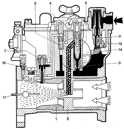
To illustrate the DCOE Series carburettors, a section is shown in Fig. 29 and a colour chart on page 46.
It is always possible to identify the main calibrated parts of a carburettor in-spite of the different systems adopted when, for instance, the barrels are vertical. In the Weber carburettor designation, the first number indicates the barrel diameter in mm at throttle level and is followed by a group of code letters and, sometimes, by a second number completing the identification.
Examples:
- 40 DCOE 32: horizontal (sidedraft) carburettor with two 40 mm barrels.
- 28/36 DLE 2: carburettor with two barrels, 28 mm primary and 36 mm secondary.
Parts are described below in the same order as given under the adjustment setting list on previous page.
1) Main or primary Venturi - Fig. 30
The main Venturi diameter - in this case, 29 mm is referred to the narrowest internal section (throat) and is selected from the results of tests run on the engine.
The diameter chosen may be:
-
greater, when maximum power at high rpm and maximum road speed are desired, or
-
smaller, when better pick-up is desired with a penalty on maximum power.
In fact, the task assigned to the main Venturi is to increase the vacuum acting on the carburettor main circuit in order to draw in and atomise the mixture; the consequence is, however, an increased resistance encountered by the flow through the carburettor. The sharper the passage section variations, the more evident are the effects of this resistance. The following relationship is thus used in calculations:
-
Main Venturi diameter = barrel diameter x 0.7 ... 0.9.
The barrel diameter depends on engine and application specifications, and for this reason it will not be possible to give any detailed description here.
However, as a preliminary selection criteria, it will prove useful to refer to the Weber Catalogue and Adjustment Setting Tables where also the other elements needed for a correct adjustment may be found.
For an acceptable adjustment setting, any reduction in main Venturi diameter must be accompanied by a reduction in the diameter of the main (pilot) jet to prevent excessive mixture enrichment, as described later.
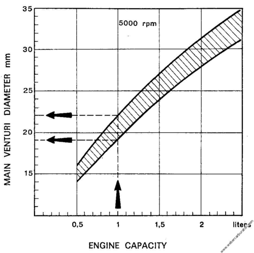
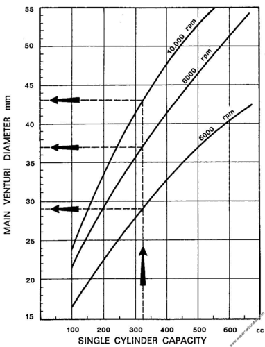
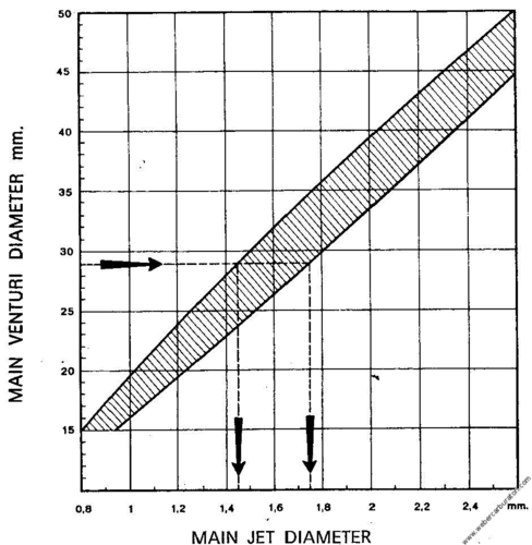
The main Venturi bears a number, stamped on its air cleaner side, showing its major striction size or smallest diameter. When the main Venturi is cast integral with the carburettor body this diameter is stamped on the outside face of the body casting, as is the case, for instance, of units 30 DIC and 26 IMB. Two graphs are provided for an approximate determination of main Venturi diameters:
- the first (Fig. 31) covers current types of 2 to 6 cylinder engines fitting a single-barrel carburettor and
- the second (Fig. 32) covers sports engines designed on the singlefeed system, namely, one carburettor barrel to each cylinder.
In both graphs, engines operate on the fourstroke cycle and are not fitted with superchargers.
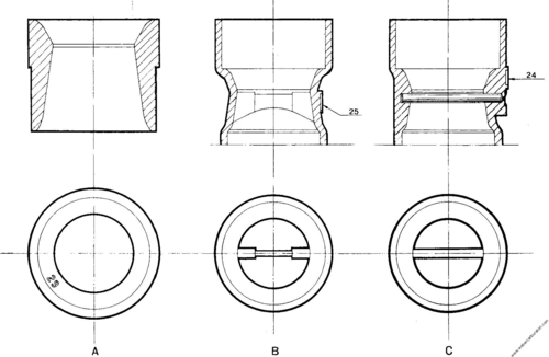
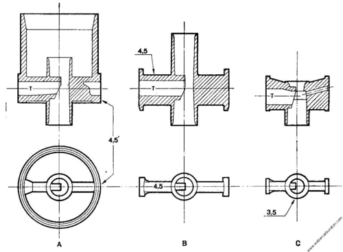
2) Auxiliary or secondary Venturi - Fig. 33
The value stamped in different locations refers to the narrowest section T of the spray nozzle through which the mixture flows and indicates that the cross-sectional area is the same as the one of a hole having the same diameter, say 4.5 mm as in A and B.
The more commonly adopted diameters fall in the range between 3 and 5 mm, depending on different requirements: the influence of the flow passage section is felt more markedly at high rpm rates. For special purposes, such as a desirable reduction in mixture rejection caused by engine pulsating induction, the elongated type of auxiliary Venturi is adopted on sports cars.
In other cases, it proves beneficial - for improved mixture distribution - to give an asymmetric shape to the auxiliary Venturi portion nearest the throttle. For the smaller carburettors, a single diameter rating is factory-set and cannot be changed.
3) Main jet - Fig. 34
This is a calibrated component of great importance which is controlled with extreme care by measuring the flow rating of every single jet: the figure stamped on its side represents the nominal diameter in 1/100 of mm of the bore through which the fuel passes and must not be measured or cleaned with any pointed metal tool.
The diameter - common values range between 0.80 and 1.80 mm - must be chosen according to the main Venturi, the air bleed jet, the number of cylinders to be fed, the grade of fuel used, etc.
Useful though approximate data for a preliminary choice may be found in the graph of Fig. 35.
A recommended procedure for testing purposes is to start with the larger diameter jet, then reducing the diameter according to requirements.
On the basis of a correct adjustment setting, it may be said that every 1 mm increase in main Venturi diameter will call for an increase of about 0.05 mm in the main jet diameter.
Whenever the diameter of the main jet, or of any other jet, must be increased or decreased, it will be necessary to change the jet(s) with genuine Weber spare(s) and avoiding any use of pointed tools, etc.
4) Air correction jet - Fig. 36
The more commonly adopted diameters for this jet fall in the 1.50 to 2.30 mm range; by increasing the diameter of this jet, the mixture is weakened more at higher than lower engine rpm rates whereas by increasing the diameter of the main jet the mixture is enriched uniformly at both high and low engine rpm rates.
The influence of the two jets thus used to best advantage in controlling adjustment setting and, for small variations, a 0.15 mm increase in the air correction jet diameter may be equivalent to an 0.05 mm reduction in the main jet diameter, considering the more common adjustment settings.
5) Emulsion tube
Its task is to emulsify the previously metered air issuing from the bleed jet with the fuel coming from the main jet. Its influence is more marked at small and average throttle opening angles and during accelerations (pick ups). Significant factors are:
-
Location and size of the orifices nearest the air bleed jet
-
Maximum outside diameter
-
Location and size of orifices nearest the main jet. Some indicative information is provided below in tabulated form as an aid in selecting the right type of emulsion tube. Designation codes are subdivided in three columns, one for each series of tubes used by Weber.
Designations - for instance F11 - are not progressive but only indicative and there are also some performance differences between the tubes grouped in any of the blocks.
Important note:
Frequently, any change in emulsion tube must be accompanied by a variation in the diameter of the main jet or air correction jet.
Indicative table for emulsion tube selection
| Weber Part Numbers | |||
|---|---|---|---|
| 61440... | 61450... | 61455... | |
| Usual Application |  for: 40-46 IDA (3V) 40 IF (3V) and a lot of the remaining carb. types for: 40-46 IDA (3V) 40 IF (3V) and a lot of the remaining carb. types |
 only for: DCOE-DCNF IDF-IDA (2V) DATRA-DFTA DMTR-DMTRA only for: DCOE-DCNF IDF-IDA (2V) DATRA-DFTA DMTR-DMTRA |
 only for: DCD-DCZ carb. types only for: DCD-DCZ carb. types |
| Current Usage | F2 F3 F6 F7 F8 F9 F15 F16 F20 F21 F24 F26 F33 F34 F35 | F2 F3 F4 F7 F9 F11 F14 F15 F16 | F8 F13 F23 F26 F30 F33 |
| For mixture enrichment at low rpm or during slight accelerations (tubes without orifices at top) | F3 F5 F7 F21 | F7 | F23 F30 |
| For mixture weakening at low rpm or during slight accelerations (tubes with orifices at top) | F20 F33 F34 | F2 F3 F11 F14 F15 F16 | F8 F26 F33 |
| Tubes with many orifices for high rpm mixture richness reductions when air bleed jet is larger than 2.00 mm | F8 F16 F20 | F11 F19 | F8 F9 F31 |
| When mixture enrichment for slight accelerations is needed, the fuel reserve in emulsion well must be increased: this is obtained by fitting a tube having small outside diameter, orifices located prevailingly in the lower portion and a larger size air bleed jet to prevent excessive mixture richness at high rpm | F3 F5 F25 | F7 F8 | F13 |
| Tubes for very large main fuel jets or for alcohol-based fuels | F2 F20 F24 F25 F26 | F2 F3 F4 F7 F17 | F8 F10 F29 |
Calibrated parts
The Weber part numbering system
All types of parts in a carburettor are given a basic five figure number which relates to the family or group to which they belong. After the five figure number there follows a three digit number which identifies the particular part in question.
Sizes are usually expressed in millimetres or fractions of a millimetre. For example, a fifty (point five mm) idle jet would be shown thus .050. A135 (one point three five mm) would be shown .135 as the size exceeds one millimetre.
For better choice, here below and on successive pages, there are drawings of all Weber emulsion tubes fitted on all range of carburettors.
Drawing and relevant tables show the following measures:
-
Height
-
External diameter
-
Diameter of the internal channel
-
Number and diameters of orifices.
At the end of the drawings there is a conversion table where is possible to find all emulsion tubes F designation in progressive order.
The basic numbers for calibrated parts are as follows
| Family | Basic figure number |
|---|---|
| Emulsion tubes | 61440, 61450, 61455 |
| Aux. venturis | 68819 ÷ 71124 |
| Chokes | 71502 ÷ 73204 |
| Main jets | 73401, 73405, 73801 |
| Idle jets | 74401 ÷ 74839 |
| Acc. pump jets | 76201 ÷ 76801 |
| Air correction jets | 77201 ÷ 77502 |
| Needle valves | 79401 ÷ 79516 |
Reference tables
61440.xxx References
| Part Number | Types | mm. | Nr. holes x diameter (1/100 of mm.) | ||||||||
|---|---|---|---|---|---|---|---|---|---|---|---|
| A | B | C | D | E | F | G | H | I | L | ||
| 61440.120 | F3 | 4.5 | 3.5 | 4x125 | 2x100 | 2x100 | 4x100 | ||||
| 61440.150 .151 .153 .154 |
F1 F26 F49 F58 |
4.5 4.5 4.5 4.5 |
2.75 2.75 2.75 2.75 |
1x100 1x100 1x100 2x100 |
1x100 2x100 1x100 2x100 |
2x140 4x140 2x140 2x140 |
2x100 4x100 2x100 2x100 |
2x100 2x100 |
2x100 2x100 |
||
| 61440.155 | F63 | 4.5 | 2.75 | 1x100 | 1x100 | 2x150 | 2x150 | 2x125 | |||
| 61440.166 | F2 | 4.5 | 2.75 | 4x100 | 4x100 | 4x140 | 4x100 | ||||
| 61440.181 .182 |
F3 F5 |
4.5 4.25 |
2.75 2.75 |
4x100 4x100 |
4x100 4x100 |
4x140 4x140 |
4x100 4x100 |
||||
| 61440.196 .197 |
F4 F70 |
4.75 5 |
2.75 2.75 |
4x100 4x100 |
4x100 4x100 |
4x140 | 4x140 | 4x120 |
4x120 |
||

| Part Number | Types | mm. | Nr. holes x diameter (1/100 of mm.) | ||||||||
|---|---|---|---|---|---|---|---|---|---|---|---|
| A | B | C | D | E | F | G | H | I | L | ||
| 61440.211 .212 .213 .217 .218 .219 .223 |
F6 F8 F24 F53 F56 F57 F80 |
4.25 5 4 4.5 4.5 4.5 4 |
2.75 3 2.75 2.75 2.75 2.75 2.75 |
2x100 2x125 2x100 2x100 2x100 2x100 2x100 |
4x100 4x125 4x100 4x100 4x100 4x100 4x100 |
4x140 4x140 4x140 4x140 4x140 4x140 4x140 |
4x100 4x100 4x100 4x115 4x150 4x130 4x150 |
||||
| 61440.216 .224 |
F50 F81 |
4.5 4.5 |
2.75 2.75 |
- 4x140 |
4x140 4x140 |
4x140 4x140 |
4x140 4x140 |
4x140 4x140 |
4x140 4x140 |
||
| 61440.220 .222 |
F66 F78 |
4.5 4.5 |
2.75 2.75 |
4x160 2x120 |
4x120 4x120 |
4x120 2x120 |
- 2x120 |
||||
| 61440.226 | F7 | 4.5 | 2.75 | 4x100 | 4x140 | 4x100 | |||||
| 61440.229 | F87 | 4.5 | 2.75 | 2x100 | 4x100 | 4x140 | 4x150 | 4x150 | |||
| 61440.241 .246 .249 |
F9 F51 F75 |
4.5 4.5 4.5 |
3.5 3.5 3.5 |
2x100 2x100 2x100 |
2x100 2x100 2x100 |
2x100 2x100 2x100 |
2x115 2x115 2x115 |
- 4x100 - |
|||
| 61440.242 | F40 | 4.5 | 3.5 | 2x100 | 2x100 | 2x100 | 2x115 | ||||

| Part Number | Types | mm. | Nr. holes x diameter (1/100 of mm.) | ||||||||
|---|---|---|---|---|---|---|---|---|---|---|---|
| A | B | C | D | E | F | G | H | I | L | ||
| 61440.243 .224 .245 |
F42 F47 F48 |
4.5 4.5 4.5 |
3.5 3.5 3.5 |
2x100 2x100 2x100 |
2x100 2x100 2x100 |
2x100 2x100 2x100 |
2x115 2x115 2x115 |
- - 4x75 |
1x50 2x100 2x100 |
||
| 61440.247 | F54 | 4.5 | 3.5 | 4x110 | 4x110 | 4x110 | 4x120 | ||||
| 61440.261 | F10 | 4.75 | 3.5 | 2x100 | 2x100 | 2x100 | 2x115 | ||||
| 61440.281 | F11 | 4.5 | 3.5 | 2x100 | 2x100 | 2x100 | 4x125 | ||||
| 61440.301 .302 .303 .304 .305 |
F14 F43 F73 F74 F84 |
5 5 5 5 4 |
3 3 3 3 3 |
2x115 2x115 2x115 2x115 2x115 |
4x115 4x140 4x140 4x140 4x140 |
2x115 2x115 4x140 2x115 4x140 |
- 2x120 4x140 2x120 4x140 |
- - - 2x100 - |
|||
| 61440.321 .328 |
F15 F68 |
75 75 |
3.50 3.50 |
- 2x100 |
2x115 2x115 |
2x115 - |
4x115 4x115 |
4x115 4x115 |
- 4x150 |
||
| 61440.323 | F52 | 4.65 | 3.50 | 2x115 | 2x115 | 4x115 | 2x75 | ||||

| Part Number | Types | mm. | Nr. holes x diameter (1/100 of mm.) | ||||||||
|---|---|---|---|---|---|---|---|---|---|---|---|
| A | B | C | D | E | F | G | H | I | L | ||
| 61440.325 .326 .329 |
F60 F61 F82 |
4.1 4.1 4.1 |
2.50 2.50 2.50 |
- - 4x100 |
2x115 2x115 2x115 |
2x115 2x115 2x115 |
4x115 4x115 4x115 |
4x115 - 4x115 |
|||
| 61440.341 .343 .344 |
F16 F71 F85 |
4.75 4.75 4.75 |
3.25 3.25 3.25 |
4x115 4x115 4x140 |
4x115 4x115 4x115 |
4x115 4x115 4x115 |
- 4x115 4x115 |
||||
| 61440.351 .352 |
F17 F38 |
4.5 4.5 |
3.25 3.25 |
2x115 2x115 |
2x115 2x115 |
2x115 2x115 |
- 1x125 |
||||
| 61440.351 .352 |
F17 F38 |
4.5 4.5 |
3.25 3.25 |
2x115 2x115 |
2x115 2x115 |
2x115 2x115 |
- 1x125 |
||||
| 61440.356 .357 |
F18 F67 |
4.65 4.65 |
3.5 3.5 |
2x115 2x115 |
2x115 2x115 |
2x115 2x115 |
4x115 4x115 |
4x115 4x115 |
- 4x150 |
||
| 61440.359 | F86 | 4.65 | 3.5 | 4x115 | 2x115 | 2x115 | 1x115 | 4x140 | |||
| 61440.365 | F20 | 4.5 | 3 | 4x115 | 4x115 | 4x115 | 4x115 | ||||
| 61440.371 .372 |
F21 F23 |
4.5 4.5 |
2.75 2.75 |
4x100 4x100 |
4x100 4x100 |
4x100 4x100 |
2x100 2x100 |
- 2x100 |
|||


| Part Number | Types | mm. | Nr. holes x diameter (1/100 of mm.) | ||||||||
|---|---|---|---|---|---|---|---|---|---|---|---|
| A | B | C | D | E | F | G | H | I | L | ||
| 61440.452 .471 |
F3 F2 |
4.5 4.5 |
2.75 2.75 |
2x100 2x100 |
4x100 4x100 |
4x100 4x100 |
4x100 4x100 |
2x120 - |
|||
| 61440.454 | F77 | 4.7 | 3.7 | 4x130 | 4x100 | 4x100 | 4x100 | 4x100 | 4x130 | 4x150 | 2x100 |
| 61440.488 | F25 | 4 | 2.75 | 4x140 | 4x140 | 2x100 | |||||
| 61440.501 | F29 | 4.5 | 3.5 | 4x100 | 4x100 | ||||||
| 61440.502 | F33 | 4.5 | 3.5 | 4x120 | 4x120 | ||||||
| 61440.515 | F30 | 4.5 | 3.5 | 2x100 | 2x100 | 2x100 | 2x115 | 1x120 | |||
| 61440.525 .526 |
F34 | F35 | 4.5 4.5 |
2.75 2.75 |
2x100 - |
2x100 2x100 |
2x100 2x100 |
2x100 - |
|||


61450.xxx References
| Part Number | Types | mm. | Nr. holes x diameter (1/100 of mm.) | ||||||||
|---|---|---|---|---|---|---|---|---|---|---|---|
| A | B | C | D | E | F | G | H | I | L | ||
| 61450.026 .027 .028 .029 .030 .031 .032 |
F1 F2 F3 F5 F9 F11 F15 |
7.5 7.5 7.5 7.5 8.2 8 8 |
3 3 3 3 3 3 3 |
2x100 2x100 2x100 - 2x100 2x100 2x100 |
- 2x100 2x100 2x100 2x100 2x100 2x100 |
8x100 8x100 8x100 8x100 8x100 8x100 8x100 |
- - 4x100 4x100 - 4x100 - |
4x250 4x250 4x250 4x250 4x250 4x250 4x250 |
|||
| 61450.036 | F50 | 8.1 | 3 | 4x110 | 4x110 | 4x110 | 4x110 | 4x80 | 4x200 | ||
| 61450.051 .052 .053 .054 |
F4 F17 F20 F34 |
7.5 6.5 7.5 7.5 |
3 3 3 4 |
2x100 2x100 2x100 2x100 |
2x100 2x100 2x100 2x100 |
8x100 8x100 8x100 8x100 |
4x100 4x100 4x100 4x100 |
4x100 4x100 4x100 4x100 |
4x100 4x100 - 4x100 |
4x250 4x250 4x250 4x250 |
|
| 61450.057 .058 |
F41 F47 |
8.1 8 |
3 3 |
2x80 2x80 |
4x250 4x250 |
4x100 4x100 |
4x100 4x100 |
4x80 4x80 |
4x200 4x200 |
||
| 61450.071 | F6 | 8.3 | 3 | 4x100 | 4x100 | 4x100 | 4x100 | 4x100 | 4x250 | ||
| 61450.091 .092 |
F7 F8 |
7.5 7.5 |
3 3 |
- 2x100 |
8x100 8x100 |
4x100 4x100 |
4x250 4x250 |
||||
| 61450.111 | F10 | 7.5 | 3 | 4x100 | 8x100 | 4x250 | |||||


| Part Number | Types | mm. | Nr. holes x diameter (1/100 of mm.) | ||||||||
|---|---|---|---|---|---|---|---|---|---|---|---|
| A | B | C | D | E | F | G | H | I | L | ||
| 61450.131 | F12 | 7.5 | 5 | 8x100 | 4x250 | ||||||
| 61450.166 | F14 | 8.2 | 3 | 8x100 | 4x250 | ||||||
| 61450.167 | F49 | 8.2 | 3 | 2x125 | 2x80 | 2x80 | 4x90 | 4x90 | 4x250 | ||
| 61450.181 | F16 | 8.2 | 3 | 8x100 | 4x250 | ||||||
| 61450.210 | F19 | 8.2 | 3.5 | 8x100 | 4x100 | 4x100 | 4x100 | 4x250 | |||
| 61450.221 .222 |
F21 F22 |
5.7 6 |
3.5 3.5 |
4x120 4x120 |
4x120 4x120 |
4x200 4x200 |
|||||
| 61450.224 .226 .234 |
F24 F26 F38 |
5 5 5 |
3 3 3 |
4x150 4x150 2x150 |
- - 2x150 |
4x150 4x150 4x150 |
- - 4x150 |
4x200 4x200 4x200 |
|||


| Part Number | Types | mm. | Nr. holes x diameter (1/100 of mm.) | ||||||||
|---|---|---|---|---|---|---|---|---|---|---|---|
| A | B | C | D | E | F | G | H | I | L | ||
| 61450.225 .228 |
F25 F28 |
6 6 |
3.5 3.5 |
4x120 4x120 |
4x120 4x120 |
- 4x120 |
4x200 4x200 |
||||
| 61450.227 .229 .232 .238 .241 |
F27 F30 F36 F44 F46 |
6.2 6.2 5.9 5.5 3.5 |
3.5 3.5 3.5 3.5 3.5 |
4x115 4x140 - 4x140 - |
4x115 4x140 2x140 4x140 2x140 |
4x115 4x115 2x115 4x115 2x115 |
2x115 2x115 2x115 2x115 2x115 |
- 2x115 - 2x115 - |
4x150 4x150 4x150 4x150 4x150 |
||
| 61450.230 | F32 | 7 | 3 | 8x100 | 4x100 | 4x100 | 4x250 | ||||
| 61450.231 | F33 | 5 | 3 | 2x100 | 2x100 | 4x120 | 4x150 | 4x200 | |||
| 61450.235 | F39 | 5 | 3 | 1x150 | 4x150 | 4x150 | 4x150 | 4x200 | |||
| 61450.236 | F42 | 6.2 | 3.5 | 4x200 | 4x200 | 4x160 | 4x140 | 4x150 | 4x150 | 4x180 | |
| 61450.237 | F43 | 6.2 | 3.5 | 4x180 | 4x200 | 4x120 | 4x140 | 4x115 | 2x115 | 4x150 | |


| Part Number | Types | mm. | Nr. holes x diameter (1/100 of mm.) | ||||||||
|---|---|---|---|---|---|---|---|---|---|---|---|
| A | B | C | D | E | F | G | H | I | L | ||
| 61450.239 | F30 spec. | 6.2 | 3.5 | 4x140 | 4x140 | 2x115 | 2x115 | 2x115 | 4x150 | ||
| 61450.240 | F45 | 5.3 | 3.5 | 4x120 | 4x120 | 4x200 | |||||
| 61450.242 | F46 spec. | 6 | 3.5 | 2x140 | 2x115 | 2x115 | 4x150 | ||||

61455.xxx References
| Part Number | Types | mm. | Nr. holes x diameter (1/100 of mm.) | ||||||||
|---|---|---|---|---|---|---|---|---|---|---|---|
| A | B | C | D | E | F | G | H | I | L | ||
| 61455.001 .002 .003 .005 .006 .007 .008 |
F4 F5 F6 F8 F9 F10 F11 |
5.25 6.25 5.25 5.25 6.25 4 4 |
2.5 2.5 2.5 2.5 2.5 2.5 2.5 |
- - 4x125 4x125 4x125 - - |
4x100 4x100 4x100 4x100 4x100 4x95 4x95 |
- 4x125 - 4x125 4x125 4x125 4x125 |
4x100 4x100 4x100 4x100 4x100 4x95 - |
4x125 4x125 4x125 4x125 4x125 4x125 - |
|||
| 61455.031 | F7 | 5.5 | 3 | 4x100 | 4x100 | 4x100 | 4x100 | 4x100 | |||
| 61455.046 | F13 | 5.5 | 3.5 | 4x125 | 4x125 | 4x125 | 4x125 | ||||
| 61455.061 .062 |
F14 F18 |
6 5.5 |
3.5 3.5 |
4x100 4x125 |
4x100 4x125 |
4x100 4x100 |
2x100 2x100 |
||||

| Part Number | Types | mm. | Nr. holes x diameter (1/100 of mm.) | ||||||||
|---|---|---|---|---|---|---|---|---|---|---|---|
| A | B | C | D | E | F | G | H | I | L | ||
| 61455.091 | F17 | 6 | 3.5 | 4x140 | 4x140 | 4x140 | 2x100 | ||||
| 61455.106 | F17 | 6 | 3.5 | 4x200 | 4x100 | ||||||
| 61455.121 | F20 | 6 | 3.5 | 4x100 | 4x100 | 4x100 | |||||
| 61455.136 .137 .138 .139 |
F22 F25 F26 F33 |
6 6 5.75 5.75 |
3.5 3.5 3.5 3.5 |
- 4x100 - - |
4x125 4x125 4x125 4x125 |
4x125 - 4x125 4x125 |
4x125 - 4x125 4x125 |
4x125 - 4x125 - |
4x125 - 4x125 - |
||
| 61455.151 .152 |
F23 F30 |
5.5 5.5 |
3.5 3.5 |
2x115 4x115 |
2x100 4x100 |
2x100 4x100 |
2x100 4x100 |
||||
| 61455.181 | F27 | 5.5 | 3.5 | 2x125 | 2x125 | 4x125 | 4x125 | ||||
| 61455.196 | F28 | 6 | 3.5 | 4x150 | |||||||


| Part Number | Types | mm. | Nr. holes x diameter (1/100 of mm.) | ||||||||
|---|---|---|---|---|---|---|---|---|---|---|---|
| A | B | C | D | E | F | G | H | I | L | ||
| 61455.211 | 5 | 3.5 | 4x100 | 4x100 | 4x100 | 2x100 | |||||
| 61455.231 | F31 | 5.5 | 3.5 | 4x125 | 4x125 | 4x125 | 4x125 | 4x125 | |||
| 61455.351 .352 .353 |
F1 F2 F3 |
4.5 4.75 4 |
2.5 2.5 2.5 |
4x100 4x100 4x100 |
4x100 - 4x100 |
4x100 4x100 4x100 |
4x100 4x100 4x100 |
||||
| 61455.366 | F16 | 5.35 | 2.5 | 4x100 | 4x100 | 4x100 | 4x100 | ||||
| 61455.421 | F1 | 4.5 | 2.5 | 4x100 | 4x140 | 4x140 | 4x100 | ||||


| Part Number | Types | mm. | Nr. holes x diameter (1/100 of mm.) | ||||||||
|---|---|---|---|---|---|---|---|---|---|---|---|
| A | B | C | D | E | F | G | H | I | L | ||
Idle Jets
Idle Jets
| Carb. Type | Basic Part Number | Sizes available (in mm.) |
|---|---|---|
| 28/36 DCB-DCD, DCHE, ICF, ICP, IMB, IMPE, 36 DCD, 40 DCN, DCZ | 74401 | 0.40, 0.45, 0.47. 0.50, 0.55, 0.60, 0.65, 0.70, 0.75, 0.80, 0.90, 0.95. 1.00, 1.20, 1.25 |
| ADC, ADF, ADFA, ADL, ADLA, ADLD, DAC, DAR. DARA, DAT, DATA, DATR, DATRA, DCOF, DFAV, DFC, DFE, DFM, DFT, DFTA: DFTH, DFTM, DFV, DGAR, DGAS, DGAV. DGF, DGMS, DGS, DGV, DHS, DHSA, DHTA, DIC, DICA, DMS, DIVISA, DMTC, DMTE. DMTL, DMTR, DMTRA, DMTT, DPS, DRT, DRTC, DRTM, DSTA, IBA, ICB, ICEV, ICR, IDAP, IDT, TL , TLA, TLC, TLF, 3 Barrel Carburettors | 74403 | 0.00, 0.40: 0.42, 0.45, 0.47, 0.50, 0.52, 0.55, 0.57, 0.60: 0.65, 0.70. 0.75, 0.80, 0.85, 0.90, 0.95, 1.00 |
| TLDR | 74704 | 50 |
| 28/36 DM-DMA, DCA, DCNF, DCNFA, DCNV, DCNVH, IDF | 74405 | 0.40, 0.42, 0.45, 0.47, 0.50, 0.52, 0.55, 0.57, 0.60. 0.65, 0.70 |
| ADF, ADS, DIR | 74407 | 0.40.0.45, 0.50, 0.55 |
| ADF, ADSD, DIR, DMS | 74408 | 0.45, 0.47, 0.50, 0.55 |
| ADFA. ADL, ADLA, ADHA, DARA, DGF DGAR, DGS, DIR, DPS, IBF, IBSA, IBSH, IBP, ICH | 74409 | 0.40, 0.42 0.45, 0.47, 0.50, 0.52, 0.55, 0.57, 0.60 |
| 48 IDA (idle jet) | 74823 | 0.40, 0.45, 0.50, 0.55, 0.6Q 0.65, 0.70, 0.75, 0.80 |
| 48 IDA (idle jet holder) | 77903 | 0.60, 1.00. 1.10, 1.20, 1.25, 1.50 |
Idle Jets for DCOE series carburettors

| Idle speed air jet dia. in mm. | F code | |
|---|---|---|
| 0.70 | F6 | |
| 0.90 | F12 | |
| 1.00 | F9 | |
| more common | 1.20 | F8 F11 F14 |
| 1.30 | F13 | |
| 1.40 | F2 F4 | |
| 1.60 | F5 | |
| 1.70 | F7 | |
| 2.9 | F1 | |
| 2.30 | F3 | |
Idle Jets
| Basic Part Number | Type | A | B | C | T Sizes available (mm.) | |
|---|---|---|---|---|---|---|
| Φ (mm.) | Φ (mm.) | Nr. holes | Φ (mm.) | |||
| 74814. ... | F1 | 1.40 | 2 | 1.40 | 0.00, 0.30, 0.35, 0.40, 0.45, 0.50, 0.52, 0.55,0.60, 0.65, 0.70, 0.75, 0.80, 0.85, 0.90, 0.95,1.00, 1.10, 1.20, 1.30, 1.35, 1.40, 1.50, 1.60, 1.70 | |
| 74815.... | F2 | 1.50 | 1 | 1.40 | ||
| 74816.... | F3 | 1.40 | 2 | 1.60 | ||
| 74817. ... | F4 | 2.00 | 1 | 1.40 | ||
| 74818.... | F5 | 1.40 | 1 | 1.60 | ||
| 74819.... | F6 | 2.00 | 1 | 0.70 | ||
| 74820.... | F7 | 2.00 | 2 | 1.20 | ||
| 74821.... | F8 | 2.00 | 1 | 1.20 | ||
| 74822.... | F9 | 2.00 | 1 | 1.00 | ||
| 74824.... | F11 | 1.50 | 1 | 1.20 | ||
| 74825.... | F12 | 1.50 | 1 | 0.90 | ||
| 74826.... | F13 | 2.00 | 2 | 0.90 | ||
| 74827.... | F14 | 1.70 | 1 | 1.20 | ||
| 74828.... | F15 | 2.00 | 2 | 1.05 | ||
| 74829.... | F16 | 2.10 | 2 | 1.30 | ||
| 74830. ... | F17 | 2.10 | 2 | 1.35 | 0.00, 0.45, 0.47, 0.50, 0.55, 0.57, 0.59 | |
| 74831.... | F18 | 2.10 | 2 | 1.60 | ||
| 74832.... | F19 | 2.00 | 1 | 1.20 | ||
| 74833.... | F21 | 2.10 | 4 | 1.10 | ||
| 74834.... | F22 | 2.10 | 4 | 1.20 | ||
| 74835.... | F23 | 2.00 | 1 | 1.25 | ||
| 74836.... | F24 | 2.00 | 1 | 1.55 | ||
| 74837.... | F25 | 2.00 | 1 | 1.50 | ||
| 74838.... | F26 | 2.00 | 2 | 1.25 | ||
| 74839.... | F27 | 2.00 | 1 | 1.60 | ||
Idle Jets
Idle Jets
| Carb. Type | Basic Part Number | Sizes available (in mm.) |
|---|---|---|
| 28/36 DCB-DCD, DCHE, ICF, ICP, IMB, IMPE, 36 DCD, 40 DCN, DCZ | 74401 | 0.40, 0.45, 0.47. 0.50, 0.55, 0.60, 0.65, 0.70, 0.75, 0.80, 0.90, 0.95. 1.00, 1.20, 1.25 |
| ADC, ADF, ADFA, ADL, ADLA, ADLD, DAC, DAR. DARA, DAT, DATA, DATR, DATRA, DCOF, DFAV, DFC, DFE, DFM, DFT, DFTA: DFTH, DFTM, DFV, DGAR, DGAS, DGAV. DGF, DGMS, DGS, DGV, DHS, DHSA, DHTA, DIC, DICA, DMS, DIVISA, DMTC, DMTE. DMTL, DMTR, DMTRA, DMTT, DPS, DRT, DRTC, DRTM, DSTA, IBA, ICB, ICEV, ICR, IDAP, IDT, TL , TLA, TLC, TLF, 3 Barrel Carburettors | 74403 | 0.00, 0.40: 0.42, 0.45, 0.47, 0.50, 0.52, 0.55, 0.57, 0.60: 0.65, 0.70. 0.75, 0.80, 0.85, 0.90, 0.95, 1.00 |
| TLDR | 74704 | 50 |
| 28/36 DM-DMA, DCA, DCNF, DCNFA, DCNV, DCNVH, IDF | 74405 | 0.40, 0.42, 0.45, 0.47, 0.50, 0.52, 0.55, 0.57, 0.60. 0.65, 0.70 |
| ADF, ADS, DIR | 74407 | 0.40.0.45, 0.50, 0.55 |
| ADF, ADSD, DIR, DMS | 74408 | 0.45, 0.47, 0.50, 0.55 |
| ADFA. ADL, ADLA, ADHA, DARA, DGF DGAR, DGS, DIR, DPS, IBF, IBSA, IBSH, IBP, ICH | 74409 | 0.40, 0.42 0.45, 0.47, 0.50, 0.52, 0.55, 0.57, 0.60 |
| 48 IDA (idle jet) | 74823 | 0.40, 0.45, 0.50, 0.55, 0.6Q 0.65, 0.70, 0.75, 0.80 |
| 48 IDA (idle jet holder) | 77903 | 0.60, 1.00. 1.10, 1.20, 1.25, 1.50 |
Idle Jets for DCOE series carburettors
| Idle speed air jet dia. in mm. | F code | |
|---|---|---|
| 0.70 | F6 | |
| 0.90 | F12 | |
| 1.00 | F9 | |
| more common | 1.20 | F8 F11 F14 |
| 1.30 | F13 | |
| 1.40 | F2 F4 | |
| 1.60 | F5 | |
| 1.70 | F7 | |
| 2.9 | F1 | |
| 2.30 | F3 | |
Idle Jets
| Basic Part Number | Type | A | B | C | T Sizes available (mm.) | |
|---|---|---|---|---|---|---|
| Φ (mm.) | Φ (mm.) | Nr. holes | Φ (mm.) | |||
| 74814. ... | F1 | 1.40 | 2 | 1.40 | 0.00, 0.30, 0.35, 0.40, 0.45, 0.50, 0.52, 0.55,0.60, 0.65, 0.70, 0.75, 0.80, 0.85, 0.90, 0.95,1.00, 1.10, 1.20, 1.30, 1.35, 1.40, 1.50, 1.60, 1.70 | |
| 74815.... | F2 | 1.50 | 1 | 1.40 | ||
| 74816.... | F3 | 1.40 | 2 | 1.60 | ||
| 74817. ... | F4 | 2.00 | 1 | 1.40 | ||
| 74818.... | F5 | 1.40 | 1 | 1.60 | ||
| 74819.... | F6 | 2.00 | 1 | 0.70 | ||
| 74820.... | F7 | 2.00 | 2 | 1.20 | ||
| 74821.... | F8 | 2.00 | 1 | 1.20 | ||
| 74822.... | F9 | 2.00 | 1 | 1.00 | ||
| 74824.... | F11 | 1.50 | 1 | 1.20 | ||
| 74825.... | F12 | 1.50 | 1 | 0.90 | ||
| 74826.... | F13 | 2.00 | 2 | 0.90 | ||
| 74827.... | F14 | 1.70 | 1 | 1.20 | ||
| 74828.... | F15 | 2.00 | 2 | 1.05 | ||
| 74829.... | F16 | 2.10 | 2 | 1.30 | ||
| 74830. ... | F17 | 2.10 | 2 | 1.35 | 0.00, 0.45, 0.47, 0.50, 0.55, 0.57, 0.59 | |
| 74831.... | F18 | 2.10 | 2 | 1.60 | ||
| 74832.... | F19 | 2.00 | 1 | 1.20 | ||
| 74833.... | F21 | 2.10 | 4 | 1.10 | ||
| 74834.... | F22 | 2.10 | 4 | 1.20 | ||
| 74835.... | F23 | 2.00 | 1 | 1.25 | ||
| 74836.... | F24 | 2.00 | 1 | 1.55 | ||
| 74837.... | F25 | 2.00 | 1 | 1.50 | ||
| 74838.... | F26 | 2.00 | 2 | 1.25 | ||
| 74839.... | F27 | 2.00 | 1 | 1.60 | ||
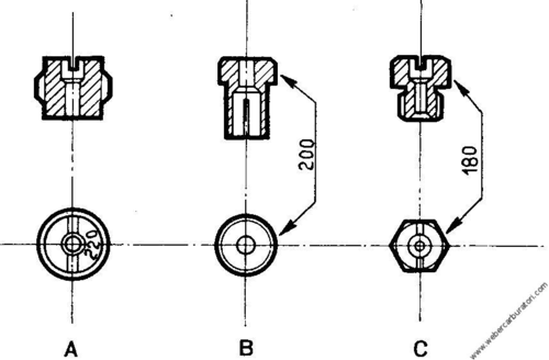
6) Idle Jet - Figs 37 and 38
Two widely used arrangements are illustrated in Figs. 37 and 38: the first shows a DCOE series carburettor with idle jet of the type incorporating the idle air jet: in the second, this air jet is separate. The idle jet belonging to the adjustment setting being considered here, has a diameter of 0.50 mm and designation 50 F11. Following is a tabulation showing - next to every F designation - the respective and equivalent air jet diameter.


In the case of adjustment settings in which the idle fuel jet is separate from the idle air jet, only the value in mm of the latter jet is specified. The idle fuel jet diameter is usually included between 0.40 and 0.70 mm: this jet strongly affects the idle speed mixture metering and thf entire transition (or progression) stage. The idle air jet, instead, comes into play on the higher side of the transition period. By transition stage is intended the carburettor operation range that starts from the idle speed rate and ends slightly beyond the point of main circuit priming.
Idle speed circuit feed - Generally, in applications where a single carburettor barrel feeds two or more engine cylinders, the idle speed circuit receives its fuel supply from the main well, in a location between the main fuel jet and the lower end of the emulsion tube (Fig. 38). In sports engine applications where each carburettor barrel feeds a single cylinder, the part-load operation mixture tends to be weak; thus, the idle speed circuit receives its fuel supply directly from the constant-level float chamber (Fig. 37), in the majority o - cases. In some applications, designers prefer a compound system in which the idle jet is fed simultaneously from both the float chamber and the well.
Engine idle speed rate adjustments
This brief description must be completed by the more detailed instructions outlined on page 55 under Part Three.
The engine must be connected to a revolution counter and be running at rated operation temperature. Engine idle speed rpm is set by a speed rate adjusting screw to the value specified by the Manufacturer: between 600-800 rpm for touring car engines and about 1000 rpm or more for sports car engines. First, turn in or out slowly the idle mixture adjusting screw to find the position in which it gives the highest possible rpm rate. If the speed must be reduced to the previous mentioned rates, operate on the speed adjusting screw, then check again for proper metering by the mixture adjusting screw. Idle speed mixture is correct when the engine runs smoothly and upon turning in or out the mixture screw - that is, weakening or enriching the mixture strength - the rpm rate drops and becomes erratic.
Transition (or progression) stage check - Once the idle speed rate is properly set, increase engine rpm rate by the speed adjusting screw up to the point at which the mixture is about to issue from the auxiliary Venturi spray tube (say, 300 rpm above idle rate): now, check for correct metering by turning slowly in or out the mixture adjusting screw. If by screwing in the speed increases it means that progression is rich while it is weak if the mixture screw must be backed out (open) to obtain a speed increase: progression will instead be correct if by turning the mixture adjusting screw either way the rpm rate will drop. From the results of this check, the transition stage may be enriched by increasing the idle fuel jet diameter or by reducing the idle air jet diameter. It is of course possible to weaken the transition stage by proceeding in the opposite way.
Sometimes it may prove necessary to re-locate the transition orifice with respect to the throttle valve edge, for instance, when a carburettor servicing includes polishing of the barrel and throttle valve replacement. Such condition is illustrated in Figs. 39 and 40. In Fig. 39-A the transition orifice is blanked out by the throttle plate edge set in idle speed position as it should be for correct operation.


In Fig. 39-B the transition orifice results offset upwards (upstream of throttle) and though idle speed operation is quite smooth "flat spots" will be experienced as soon as the throttle begins to open, owing to an excessively weak mixture. In fact, in this case the orifice is acted upon too late by the depression existing beneath the throttle plate.
In Fig. 39-C the transition orifice is offset downwards (downstream of throttle) and idle speed operation is quite "rough" owing to an excessively rich mixture even with mixture adjusting screw tightened in fully (closed), as the supply from the transition orifice is too generous. The remedial actions for such conditions are:
-
case of Fig. 39-B - by trial and error cut a chamfer in throttle plate edge as shown in Fig. 40-A.
-
case of Fig. 39-C - drill a hole in throttle plate, on the side opposite the transition orifice, so that part of the air drawn in by the engine will flow through, thus allowing the throttle valve to remain closed, as shown in Fig. Fig. 40-B. Initially, this hole should have a diameter of 0.7 mm and may be increased gradually up to 1.2 - 1.5 mm, as required, but never to a diameter that would cause the throttle plate to blank out the barrel completely.
The above procedures serve to remedy slight faults and it is not possible to describe here other corrective measures such as variations in transition orifice location or diameter.
Weber throttle valve plates are stamp-marked with a value representing the lowest angle in degrees existing between closed throttle and barrel centreline - usually 78° or 85° - to prevent any replacement errors.
7-8-9) Accelerating pump jet and drain Figs. 41 and 42
The main features of accelerating pump operation are the amount of fuel injected at each stroke and the promptness and duration of each injection. When tuning up for proper adjustment settings, the pump jet and drain diameters are determined by trying to minimise, as far as practicable, the amount of fuel injected. Often, also the direction of the fuel spray proves to be a significant factor.
Generally, when engine operates at high rpm rates the pump jet (diameter between 0.35 and 1 mm) is subject to a vacuum sufficient to produce an uninterrupted flow of fuel, that is, it performs as a high speed jet and its role falls under the adjustment setting data.
If the pump supply ceases "faltering" accelerations will result with "poppings" in carburettor, followed by possible stopping of the engine. Instead, if the pump supply is excessive, acceleration will still falter and an emission of black smoke at the exhaust will mark each acceleration.
The pump drain jet (Fig. 42) which may also be of the type incorporated in intake valve assembly is selected in one of the following two settings:
-
Closed, for maximum amount of injected fuel and maximum promptness.
-
Open, with 0.35 to 1.5 mm bore, to reduce the amount of fuel and to slightly retard promptness.
Using some special provisions it is possible to measure the amount of fuel injected by the pump at every throttle opening: for the adjustment setting considered here, the value in cc referred to a single barrel is tabulated on page 20.


10) Choke jet - Fig. 43-A
The DCOE series carburettor is provided with an easy starting device (choke) of the progressive-action type consisting of two separate circuits (one to each barrel) ìn which two manually operated plungers govern the mixture rating.
The choke jet which often incorporates the emulsion jet and the air jet - may have a diameter included between 0.60 and 2 mm, thus permitting a wide range of possible adjustments to cope with different engines and starting temperatures.
An increase in choke fuel jet bore enrichens the mixture over the entire operation range whereas any variation of the choke air jet is more influential once engine is started and during its warmup period: the setting of the choke system involves several provisions such as the fuel reserve well, the arrangement of blanking element and its intervening action adjustment, a special valve for leaning out the mixture once engine is started, etc., all of which may vary from one carburettor to another.
Offset shutter valve choke - Fig. 43-B - shows a manually-controlled starting circuit of the offset shutter (or strangler) valve type The more significant factors for adjustment settings, and referred to the choke-IN condition, are:
-
Opening of the main throttle, known as the fast-idle setting: increases the idle speed rate of the engine once it has started and runs through the warm-up stage.
-
Calibrated starting spring: it is essential to establish the mixture metering needed through the choke-IN stage.
-
Stopping of the shutter valve opening to ensure appropriate meterings during warm-up at large main throttle openings.
Make sure the shutter (or strangler) valve moves freely without any binding caused by distortions, wear or dirt: for a correct adjustment of the manual control - a very important operation to prevent starting or idle speed rate difficulties - refer to the instructions given on page 54 under Part Three.

11-12) Needle valve
Through the needle valve the float regulates the admission of fuel into the bowl to keep the level constant independently of the variable engine requirements. Level maintenance is improved by adopting needle valves having the smallest diameter that still provides the fuel supply necessary for engine operation at its highest power rating.
One of the more commonly adopted diameters is 1.50 mm which is capable of supplying 25-30 litres per hour of fuel if pressure ranges between 0.15 and 0.20 kg/ sq.cm (2.1-2.8 psi): larger sizes are used for higher fuel consumption rates and fuels containing alcohols.
The needle taper point and seat are finished and checked as a pair and are not interchangeable with the respective parts of other valves. The needle valve is often damaged by engine vibrations and car motions if the float chamber is empty (LPG feed systems); in the case of sports cars transported on trucks, carburettor bowls should be filled with thin engine oil for proper protection.
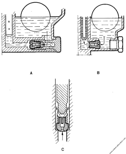
13) Fuel level in float chamber or bowl - Figs. 44-45
The fuel height in bowl must be kept at a lower level with respect to the spray nozzle bore: this prevents fuel emissions when engine is inoperative and car inclined. The level may be set at a height of less than 5-6 mm below nozzle bottom edge, depending on the type of carburettor and the performance required of the vehicle. Fuel level variations have greater influence during accelerations, idle speed and part-load/low rpm operation, with particularly marked effects in sports car applications. The Catalogue Data Sheet of each carburettor provides the necessary instructions for a correct level check which is performed as follows:
-
a) by a special gauge rod C - Fig. 44 - taking care not to push in the ball of the spring-dampened valve. Usually, the cover gasket is removed if to do this it is unnecessary to take out the float; otherwise, check with gasket tight on cover held vertical.
-
b) Inside the well, after having removed the air jet and emulsion tube, by a Vernier caliper 1 and flash-light 6, as shown in Fig. 45.
When the end of the gauge rod comes into contact with the fuel in the well it causes a sudden change in the reflected light thus giving a clear indication of the level measurement. This check is possible on almost all sports car carburettors which are often fed by an electrii pump which turns out to be extremely useful on this occasion. Check the float maximum lowering position: the needle must travel a distance equivalent to slightly more than the diameter value (in mm) stamped on its seat. If any correction is needed, bend delicately the twi tongue plates located in proximity of the fulcrum pin.

14) Float-weight
In the case of the adjustment setting being considered here, the weight is 26 grams because the float is double: the weight in grams is stamped on the tongue plate or float itself and is an adjustment setting specification for it is one of the factors establishing the fuel level in bowl. The metal float is delicate as it is made of 0.16-0.20 mm thick sheet: for this reason, absolutely avoid blowing compressed air into the float chamber or fuel inlet port when float is installed in its place. The free and unimpeded movement of the float in chamber is a design requirement.
15) Flared air horn extensions - Fig. 45
They are necessary in sports car applications where quite frequently no air cleaner is provided. Their purpose is to:
-
Improve cylinder charging
-
Limit dispersions due to mixture rejections
-
Carry the flame trap.

Hai domande o vuoi un'offerta personalizzata?
Chiamaci al numero +39 011 8224969 od invia un Fax al numero +39 011 0708775.